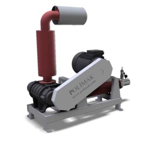
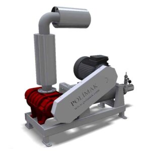
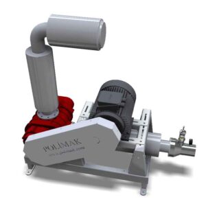
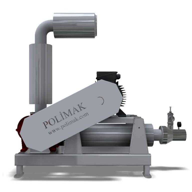
Roots blowers, also known as rotary lobe compressors, are positive displacement equipment used to generate pressurized or vacuum air for industrial processes. They operate by trapping a fixed volume of air or gas between two counter-rotating lobed rotors and forcing it through a system. This technology provides a relatively constant airflow without being affected by varying discharge pressures, making it ideal for applications requiring steady air delivery. With over a century of proven use across various industries, roots blowers remain a reliable choice for air and gas handling systems.
Roots Blowers for the Toughest Applications
Polimak’s blower systems are engineered for the most demanding industrial conditions, built to deliver exceptional performance and reliability. We manufacture roots-type positive displacement blower packages for a wide range of industrial applications, offering solutions that meet strict performance and durability requirements.
Here are some of the main advantages of Polimak blowers:
• Simple installation,
• Low maintenance requirements,
• Long-lasting, problem-free service,
• Outstanding endurance in harsh environments.
A wide range of Roots blower models and accessories are available, each tailored precisely to specific process parameters and unique site conditions, ensuring maximum efficiency and reliability in any setting.
The Working Principle of a Blower
• The blower contains two main parts called impellers, which are also known as rotors or lobes.
• These impellers spin in opposite directions, synchronized to work together smoothly.
• As they turn, a specific volume of gas gets caught between the impeller blades and the inner surface of the blower casing on the inlet side.
• The spinning impellers then move this trapped gas from the inlet toward the outlet side of the blower.
• The gas is pushed out against the system’s existing pressure, effectively increasing its pressure and flow.
• This process happens continuously, with the cycle repeating multiple times during each full rotation of the impellers, often about six times per revolution.
• Thanks to this mechanism, the blower can provide a steady and reliable flow of gas, even under challenging pressure conditions.
What is Characteristic of a Roots Blower?
• A roots blower, also known as a rotary positive displacement (PD) blower, is a type of machine designed to move a fixed volume of gas consistently through a system with each rotation.
• Unlike many compressors, a roots blower does not compress the gas internally within the blower itself. Instead, the compression happens externally when the blower pushes the gas against a downstream resistance or restriction in the system, causing pressure to build up.
• Key characteristics of a Roots blower include:
• It delivers a constant volume of gas regardless of the pressure conditions downstream.
• The flow rate is steady and predictable, meaning it doesn’t change much even if the pressure in the system varies.
• It operates by trapping fixed amounts of gas between the rotating lobes (impellers) and the casing, then mechanically moving this volume forward with each revolution.
• Since there is no internal compression, the blower produces gas flow by displacement rather than compression within the device.
• In contrast, a centrifugal compressor behaves differently:
• It maintains a relatively constant pressure in the system.
• The flow rate varies depending on the pressure and system conditions.
• Compression of the gas occurs internally due to the centrifugal force acting on the gas as it passes through the rotating impeller.
Oil-Free Conveying
One advantage of roots blowers is that their impellers do not come into contact with each other or the housing. This means that no lubrication is needed inside the gas flow chamber. Thanks to this mechanism, oil or grease cannot mix with the conveyed air or gas. This keeps the medium pure and uncontaminated.
Roots blowers work very well in industries that require clean and hygienic conditions. Examples of these industries include aquaculture, food processing, chemical handling, and milling. This feature helps protect the quality of the materials being moved. It also supports meeting strict safety and regulatory standards in sensitive applications.
Bareshaft Blowers
Polimak offers bareshaft blowers as positive displacement blower units without any additional accessories or components attached. These bare shaft units allow for flexible integration into existing systems or custom setups according to specific requirements of the system. They provide a simple solution for users who prefer to add their own drives, couplings, or other equipment separately.
Blower Packages
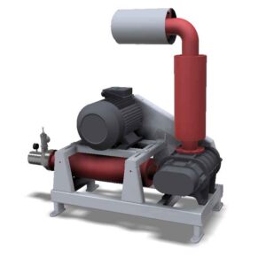
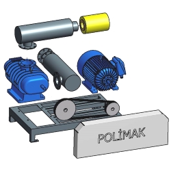
Polimak offers blower packages designed to simplify installation and ensure seamless operation. These packages come complete with everything needed for immediate use, eliminating the need to source individual components separately. The package units generally include:
• An electrical motor, perfectly matched to the blower for optimal performance;
• Silencers to reduce noise and improve workplace comfort;
• Essential accessories such as vibration isolators, couplings, and control panels.
In addition to these standard components, Polimak can customize packages to include additional features based on specific site requirements. This all-in-one solution saves time, reduces installation complexity, and guarantees that all parts work together after installation.
Advantages and Key Benefits of Polimak Roots Blowers
• Wide Air Flow Range: Polimak Roots blowers offer air flow rates from 20 m³/h up to 20,000 m³/h, making them suitable for a variety of industrial needs.
• High Pressure and Vacuum Capabilities: These blowers can provide pressure levels up to 1500 mbar and vacuum levels up to 500 mbar, providing flexibility for different applications.
• Oil-Free and Clean Gas Supply: The design ensures oil-free operation, delivering clean air and gas that is free from contamination.
• Durable Cast Iron Casing: The single-piece rigid cast iron casing provides strength and durability for long-term use.
• Efficient Heat Dissipation: The ribbed blower body enhances heat dissipation, improving overall efficiency and reliability.
• Heavy-Duty Bearings: Equipped with robust roller bearings designed to withstand heavy loads and extend service life.
• Precision 3-Lobe Rotors: The precision-machined 3-lobe rotor profiles optimize efficiency and reduce noise during operation.
• Tight Sealing: Piston ring sealing helps maintain pressure and prevents leaks for reliable performance.
• High-Quality Timing Gears: Precision-machined and heat-treated timing gears minimize vibration and maximize blower efficiency.
• Splash Oil Lubrication: This lubrication method ensures extended service life by maintaining smooth internal operation.
• Simple Installation: Designed for easy installation to save time and reduce setup costs.
• Low Maintenance: The blower’s design minimizes maintenance requirements, reducing downtime and operating expenses.
What is a Rotary Lobe Blower?
• A rotary lobe blower is a type of positive displacement pump that moves gas by trapping a fixed volume and pushing it through the system.
• It operates using two rotating impellers, also known as rotors or lobes, that spin in opposite directions without touching each other or the casing.
• As the impellers rotate, gas enters the blower through the inlet, becomes trapped between the lobes and the casing, and is then pushed toward the discharge side.
• The gas is discharged against the pressure already present in the system, making the blower suitable for systems with varying pressure conditions.
• One of the key strengths of this blower is its ability to deliver a constant, pulse-free flow regardless of changes in system pressure.
• This makes it highly effective in industrial processes where stable flow is essential, such as pneumatic conveying, wastewater treatment, and combustion air supply.
• Roots blowers are known for their simplicity, durability, and ability to perform well under continuous operation.
• They also maintain high efficiency across a wide range of flow rates, helping to reduce energy consumption and operational costs.
• Due to these features, rotary lobe blowers are a reliable choice for industries that require consistent gas movement and robust performance in tough conditions.
What is a Roots Blower?
• “Rotary lobe blowers” and “rotary lobe compressors” are common terms used in industry to refer to roots blowers.
• These machines are named after the Roots brothers, Philander and Francis Marion Roots, who were American inventors.
• In 1854, while trying to improve the efficiency of a water wheel in Connersville, Indiana, the brothers developed the initial concept for the Roots blower.
• Their goal was to create a device that could deliver a consistent stream of air to enhance mechanical performance.
• They received a patent in 1860 for their invention, officially establishing what is now known as the Roots Rotary Positive Blower Principle.
• This principle involves trapping a fixed volume of gas and forcing it through a system using synchronized, rotating impellers.
• Over time, the design has been refined, but the core operating principle remains the same and continues to be used across many industrial sectors.
• Today, the roots blower is used worldwide for its reliable performance, efficient air delivery, and versatility in handling various gases and pressures.
• It plays a key role in industries such as wastewater treatment, pneumatic conveying, cement, power generation, and more.
• The design introduced by the Roots brothers is still widely used in today’s engineering and industrial processes.
How does a Roots Blower operate?
• Twin-lobe rotary air blowers are included in the group of positive displacement machines, meaning they move a fixed volume of air or gas with each rotation.
• These blowers have two lobes or rotors housed within an oval-shaped casing, which is sealed at both ends using solid side plates.
• The lobes are synchronized using a pair of high-precision timing gears, which keep them rotating at the same speed but in opposite directions without making contact.
• As the rotors turn, they create expanding cavities on the inlet side of the housing, drawing in ambient air or gas.
• The trapped volume is then carried around the casing and compressed as it approaches the outlet, where it is pushed out against the system’s existing pressure.
• In tri-lobe blower models, each complete rotation of the rotor displaces six separate volumes of air, resulting in smooth and continuous flow.
• The tight clearances between the rotors and the casing prevent most of the discharged air from flowing backward into the inlet side.
• A very small amount of air may leak back, referred to as “slip,” but this is minimal and does not affect performance.
• This non-contact design also eliminates internal friction between the lobes, reducing wear and making oil-free operation possible in the air chamber.
• Twin-lobe and tri-lobe blowers are widely used for their reliability, steady flow output, and ability to handle varying pressure conditions without losing efficiency.
What is Positive Displacement?
• Positive displacement pumps are named for their ability to move a fixed volume of fluid without letting any of it flow back into the pump casing during operation. This means the amount of gas drawn in matches exactly the amount pushed out, creating a smooth and continuous flow. This steady transfer of a set volume is what defines positive displacement and is the reason behind the name of these pumps.
• This is made possible by the precise sealing action of rotating components such as lobes or rotors, which act like a mechanical lock, forcing the entire volume of fluid forward through the discharge line.
• In a positive displacement blower, the suction side features an expanding cavity that draws in air or gas as the rotors turn.
• On the discharge side, the cavity decreases in size, forcing the trapped volume out of the blower and into the connected system.
• Inside the blower, there is no compression of the air or gas. Instead, the blower simply transfers the gas from one side to the other by physically displacing it.
• Pressure increases only at the discharge side as the flowing gas meets resistance from the connected system.
• On the suction side, the expanding space between the lobes generates the vacuum or suction effect, making the technology suitable for both pressure and vacuum applications.
• This operating principle allows roots blowers to perform reliably in applications where a constant volume of air or gas is required, even when pressure conditions change.
• Industries such as pneumatic conveying, wastewater treatment, and combustion air supply often rely on positive displacement blowers for their durability and flow stability.
• This process delivers a continuous and predictable flow rate, making it highly preferred in demanding industrial settings regardless of pressure variations.
What is the Difference Between a Blower, Fan, and Compressor?
Compressors, fans, and blowers are essential components in a wide range of industrial systems, each serving a unique purpose depending on the process requirements. These equipment play a critical role in applications ranging from ventilation and cooling to pneumatic conveying and high-pressure gas delivery. Their widespread use across industries such as manufacturing, energy, food processing, wastewater treatment, and bulk material handling shows their importance in industrial operations.
Although they may seem similar in function (moving air or gas through a system) they differ in how they operate and the pressure levels they are designed to handle. The primary distinction lies in the compression ratio, which refers to the difference between the inlet and outlet pressures, and the method of airflow generation.
• Fans are used to move large volumes of air at relatively low pressure. They produce a small increase in pressure, just enough to circulate air or cool machinery. Common applications include HVAC systems, cooling electronics, or providing ventilation in workspaces.
• Blowers provide a moderate pressure increase, greater than a fan but less than a compressor. They are designed to push air or gas through systems with higher resistance than fans can handle. They are used in applications such as pneumatic conveying, dust collection, and aeration processes in wastewater treatment.
• Compressors are designed to raise gas pressure to much higher levels. They are used in applications where high-pressure delivery is required, such as in refrigeration systems, air tools, gas pipelines, and industrial process equipment.
Understanding the differences among these three devices is critical when selecting the right equipment for a specific application. Choosing the wrong one can lead to inefficient performance, energy waste, or even damage to the system.
Classification with Respect to Compression Ratio
Type Compression Ratio Average Operating Pressure *
Fan 0 – 1,3 0 – 0,25 bar
Blower 1,1 – 2,5 0,15 – 2 bar
Compressor > 2 3 – 12 bar
Classification with Respect to Compression Ratio
* Average operating pressure refers to the pressure range that a system typically operates within in today’s industrial applications.
With recent advancements in gas handling technologies, defining a strict pressure range, compression ratio, or method of gas pumping for each type of air handling system is challenging. For example, high-pressure fans can reach 0.4 bar and may still be classified as either a fan or a blower, depending on the industrial application, country, or sector. Another example is single-stage turbo blowers, which follow the compression principle of centrifugal compressors but are referred to as blowers instead of compressors.
To sum up,
Fans are designed to move large volumes of air or gas while producing only a small increase in pressure. They are commonly used for tasks such as circulating air in buildings, ventilating spaces, cooling machinery, and collecting dust in various industrial settings. Due to their ability to efficiently move air at low pressures, fans play a crucial role in maintaining safe and comfortable environments across many applications.
Blowers produce a moderate increase in gas pressure or vacuum, making them suitable for applications with higher system resistance than fans can handle. They are commonly used in industries such as water treatment, pneumatic conveying, and vacuum systems. Additionally, blowers play a key role in various industrial processes and supercharging applications.
Compressors increase gas pressure by compressing and reducing its volume. They are essential in many industries for supplying shop and instrument air, powering air tools, paint sprayers, and abrasive blasting equipment. Additionally, compressors are used to move refrigerants in air conditioning and refrigeration systems and to transport gases through pipelines.
Options & Accessories
Roots Blower Applications
Image Gallery
Browse through our stunning collection of product images.
INSIGHTS
Suggested Products
Explore our wide range of high-quality accessories for your bulk solids handling machinery.
FAQs
Everything you need to know about the product and billing. Can’t find the answer you’re looking for? Please chat to our friendly team.
A rotary feeder is a type of valve whose primary function is to feed or meter dry bulk solids from an upstream device to a downstream device without necessarily maintaining a pressure differential. An airlock feeder, on the other hand, is a valve that separates a pressure differential while feeding or metering dry bulk materials into a downstream system.
The blades of a rotary valve rotate inside the valve housing during operation. This rotation is driven by a motor. As the motor rotates, the rotor pockets move through the valve. Dry bulk solids are supplied to the valve from upstream equipment through its inlet and settle in the pockets. The rotor continues to rotate and discharges the dry bulk solids through the outlet port. There are two types of rotation: load side rotation and return side rotation. Load side rotation is defined as the movement of the rotor pockets from the inlet to the outlet, while return side rotation refers to the movement of the rotor pockets from the outlet port to the inlet port.
Rotary valves are used in several industries for various industrial applications. They are used for different purposes, including controlling the flow of dry bulk solids, feeding downstream systems, and maintaining a pressure differential between an upstream device and a downstream device.
These valves are typically actuated by pneumatic actuators and are used to automatically open and close the product flow to discharge material to downstream equipment.
Installed below silos or hoppers, these valves are used for maintenance operations of equipment such as rotary valves, screw feeders, etc., that are positioned below the butterfly valve.
These valves are typically actuated by pneumatic actuators and are used to automatically open and close the product flow to discharge material to downstream equipment.
In this design, the butterfly valve is sandwiched between two flanges. Rubber sealing at both faces of the valve provides a tight seal between the flanges and the wafer butterfly valve.
One side of the valve has a bolted flange connection, while the other side features a built-in short pipe designed for fixing a flexible sleeve.
These valves have bolted flange connections on both sides, making them suitable for installation on silos, hoppers, screw feeders, and similar applications.
Bulk tanker trucks or open trucks can be filled with powdered materials delivered within FIBC bags. These systems generally consist of bulk bag discharging station, mechanical or pneumatic conveyor and loading bellow. Big bag discharge station transfers the bulk solid from big bag to conveying system. Conveying system transfers it to truck loading area. And loading bellow is used to fill tanker truck without any dust emission. Since truck loading operations are done within limited time, high capacity big bag discharge systems and bulk material conveying systems are used. For short distances, screw conveyors are preferred to transfer material from big bag discharge station to truck loading chute. For long conveying distances, pneumatic conveying systems provide better service. There may exist a storage hopper or silo above bulk truck loading bellow to compensate material flow between inlet and outlet. Bulk bag discharge and truck filling systems have automatic control system that monitors product level in truck and operates all equipment accordingly. Optional weighing system can be added to measure the amount of material that is filled to truck.
Big bag discharge systems can deliver dry bulk solids in powder and granular form to weighing and batching systems. The loading hopper of the weighing system should remain full during dosing and batching. Big bag discharge systems can monitor the product level in the loading hopper and maintain a constant level automatically. Depending on the dosing speed and conveying distance, mechanical conveying systems or pneumatic loading systems may be used. Dust collectors can be employed to prevent dust emissions during hopper loading, especially for materials with high dust content.
Dry bulk packaging systems are used to fill powdered or granular materials into bags, drums, jars, sacks, etc. Bulk materials delivered in big bags must be transferred to packaging machines without interruption. The loading hopper of the packaging system should remain full during the filling and packaging process. Big bag discharge systems can monitor the product level in the loading hopper and maintain a constant level automatically. Depending on the packaging speed, mechanical conveying systems or pneumatic loading systems can be selected. Dust collectors can be used to prevent dust emissions during hopper loading, especially for materials with high dust content.
Mixer automation systems are used to mix dry bulk solids according to specific recipes. Raw materials delivered in FIBC bags can be transferred to mixing units through a combination of conveying equipment and bulk bag discharge systems. Depending on the type of application, pneumatic conveying or mechanical feeding systems can be used to fill mixers. Big bag discharge stations can be manufactured with built-in dosing systems. The amount of raw material to be loaded into the mixer is automatically controlled with the help of a weighing and dosing system. Dust collectors can be used to prevent dust emissions during the mixer filling process.
Bulk material stored in big bags can be automatically filled into small bags. Big bag discharge systems come with optional built-in bag filling units. For low filling capacities, these units are installed below the big bag discharge hopper, providing a practical and cost-effective solution. Both big bag discharging and bag filling operations can be handled by a single, compact system. For higher bag filling needs, bag filling machines are installed near the bulk bag discharge stations. Pneumatic conveying systems or mechanical conveyors can be used to transfer bulk material from the FIBC bag discharge station to the bag or sack filling system.
Mechanical conveyors can be used for silo loading from big bag discharge stations. Screw feeders, bucket elevators, rotary valves, or chain conveyors are connected to big bag discharge stations to fill silos. The selection of conveying equipment directly depends on the conveying distance, height, transferred material, and capacity. Bucket elevators are preferred for high silos, while screw feeders are preferred for shorter silos and short distances. The big bag discharge system can be installed on top of the silo for faster filling. In this case, rotary valves or butterfly valves are better choices as they provide simple flow control. Dust collection systems may be required depending on the dust content of the bulk solid. During silo loading, air content in the silo escapes to the atmosphere and carries some dust along with it. Vacuum fans and jet filters in dust collectors prevent dust emissions into the environment. The collected dust is sent back to the silo, thus preventing product loss.
Pneumatic conveying systems installed after bulk bag discharge units transfer bulk material through conveying pipelines to fill silos. This configuration is useful in applications where high transfer rates and long conveying distances are needed. In production lines where raw materials are stored in warehouses far from storage silos, bulk bag discharge stations can be installed close to the warehouses, and pneumatic conveying systems are used to fill silos from long distances. This design reduces the need for forklifts and cranes for bulk material transfer on the production site and increases overall efficiency.
Pneumatic conveying systems used for silo loading utilize blower pumps or compressors. Motor power, pipeline diameter, and equipment selection depend on the type of bulk material, transfer distance, silo height, and transfer capacity. Level sensors, jet filters, and other equipment are installed on storage silos to ensure the proper operation of the silo filling system.
Pneumatic conveying systems installed after bag dump units transfer bulk material through pipelines to fill silos. This configuration is ideal for applications requiring high transfer rates and long conveying distances. In production lines where raw materials are stored in warehouses far from storage silos, bag dump stations can be installed close to warehouses, allowing pneumatic conveying systems to transport materials over long distances. This design reduces the excessive use of forklifts and cranes for bulk material transfer within the production site, improving overall efficiency.
Pneumatic transfer systems used for silo loading utilize blower pumps or compressors. Motor power, pipeline diameter, and equipment selection depend on factors such as the type of bulk material, transfer distance, silo height, and transfer capacity. Level sensors, jet filters, and other equipment are installed on storage silos to ensure the proper operation of the silo filling system.
Mechanical conveyors can be used for silo loading from bag dump stations. In this configuration, screw feeders, bucket elevators, rotary valves, or chain conveyors are connected to bag dump stations to fill silos. The selection of conveying equipment depends on factors such as conveying distance, height, material properties, and capacity. Bucket elevators are preferred for high silos, while screw feeders are ideal for shorter silos and short distances. Bag dump systems can be installed on top of the silo for faster filling. In such cases, rotary valves or butterfly valves are better choices as they provide simple flow control.
Dust collection systems may be required depending on the dust content of the bulk solid. During silo loading, air inside the silo escapes to the atmosphere, carrying dust particles with it. Dust collectors equipped with a vacuum fan and jet filter capture airborne dust. The collected dust is returned to the silo, preventing product loss and ensuring a cleaner environment.
The inlet skirt is an optional feature designed to extend the lifespan of the flexible connector sleeve. Its upper portion is attached to the outlet port of the upstream equipment and extends down into the bin activator’s inlet port. The primary function of the inlet skirt is to serve as a protective shield, safeguarding the flexible connector seal from wear and damage.
A vibratory motor is externally mounted to the bin activator. When powered, the motor generates vibrations that facilitate a steady flow of dry bulk materials within the system. Depending on the application requirements, one or two vibratory motors can be installed externally.
To accommodate a bin activator, the cone of a silo must be shorter than usual, resulting in a wider outlet. A flange supplied with the bin activator is separately welded to the silo’s outlet, slightly above the opening, at the production site. Once installed, the vibrating bin discharger is securely bolted to the flange, ensuring a stable and reliable connection.
Special spring suspension links and an engineered polymer seal work together to create a flexible connection between a vibrating bin discharger and the equipment positioned above it.
The proper design and installation of the polyurethane seal prevent it from slipping off and ensure a secure seal, eliminating the risk of dry bulk material leakage. Additionally, the seal offers high stress resistance and long-term durability, withstanding stresses caused by motor vibrations, pressure conditions, and other operational factors.
Externally installed spring suspensions provide full resilience to the vibrations of the cone head. They ensure that the generated vibrations affect only the cone itself rather than the upstream equipment structure.
An internally tapered, conical-shaped baffle plate is positioned at the center of the bin activator’s diameter. The baffle is rigidly attached to the equipment body using structural steel components. It facilitates bulk material flow from upstream equipment by directly inducing vibrations into the material.
A secondary deflector plate reduces the weight of the bulk material in the lower portion of the bin activator by acting as a wedge beneath the material, directing it around the areas adjacent to the cone’s surface.
Polimak baffle plates are available in various configurations, including convex and cone plates, and in different angles (15°, 30°, 45°, or even 60°) depending on the flow characteristics of the handled bulk material and the specific application requirements.