PRODUCTS

Custom Designed Valves

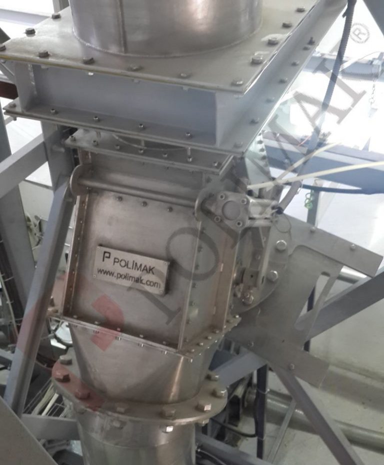
Polimak offers more than standard valve solutions. Custom designed diverter and flow control valves are developed to meet the specific demands of complex and high performance industrial environments. Polimak provides engineered solutions tailored to each application, whether the requirement involves handling abrasive materials, operating under extreme temperatures, or fitting into systems with space limitations. Options include nonstandard body geometries, specialized bore sizes, unique flange interfaces, and a wide range of compatible accessories to ensure seamless integration with existing equipment.
Every custom valve project is managed by Polimak’s engineering team, managing the entire process from identifying operational challenges to final commissioning. This process covers detailed needs assessment, design modeling, structural validation, and fabrication using high quality materials suited to the intended use case. Polimak delivers fully customized valve systems within tight deadlines, ensuring both performance reliability and long term durability in demanding industrial settings.

Application Parameters for Valve Selection

Selecting the right valve for a dry bulk handling system requires more than matching basic specification. It involves a thorough analysis of operational demands and environmental conditions. Each industrial process has its own set of challenges. Therefore, valves must be chosen based on the exact characteristics of the system they will serve. A strong understanding of flow dynamics, system layout, and working environment plays a key role in ensuring the valve will function effectively over time. Using estimations instead of precise data or incomplete information can cause poor performance, increased maintenance, or even system failure.

Accurate technical data such as material properties, flow rates, operating temperature and pressure, particle size, and available installation space are some of the most critical parameters for proper valve selection. These factors directly affect the choice of valve type, actuation method, sealing technology, and construction material. Additional factors, including the potential for corrosion, dust exposure, or contamination risks, also need to be considered during the evaluation process.

A well-designed valve does more than meet technical requirements: it supports reliable system operation, minimizes downtime, and contributes to overall process efficiency. The right decision at the selection stage leads to long-term performance and cost savings.

Some of the key considerations for valve selection in dry bulk handling systems are included below:

• Intended Use of the Valve:

Valves may be designed for shut-off, flow regulation, diverting, converging, venting, or other specific functions. Understanding the main function of the valve helps narrow down suitable types and designs.

• Material to Be Handled:

The shape of the bulk material, such as powder, granules, pellets, or flakes, influences the choice of valve. Different materials require valves that can handle their unique flow characteristics.

• Particle Size of the Bulk Material:

The size of individual particles impacts flow behavior and wear on valve components. Precise measurement guarantees the valve handles the material smoothly, preventing blockages or damage.

• Bulk Density of the Handled Material:

Knowing the bulk density helps determine the load and stresses on the valve during operation. This information guides material selection and mechanical design.

• Physical Properties of the Bulk Material:

Characteristics such as stickiness, abrasiveness, corrosiveness, dust content, and temperature are key to determining valve construction and sealing requirements. Proper consideration minimizes maintenance and extends service life.

• Inlet and Outlet Connection Shapes and Sizes:

Compatibility with existing system connections is critical. Matching these dimensions ensures a secure installation with no leakage.

• Size of Connected Equipment:

The dimensions of pipelines, chutes, hoppers, silos, or other connected units should be consistent with valve size. Proper fit maintains smooth material flow and system integrity.

• Pressure or Vacuum Levels at Ports:

Operating pressures or vacuum conditions at the valve’s inlet and outlet determine sealing and actuation methods. Valves must be capable of handling these forces safely.

• Installation Location:

Whether the valve will be installed indoors or outdoors affects material choice and protection measures. Environmental exposure can dictate corrosion resistance and durability needs.

• Type of Application:

Applications in food processing, sanitary environments, or explosive zones require valves that meet specific regulatory standards. Meeting standards guarantees safety and maintains product quality.

• Site Conditions:

Temperature extremes in the environment, moisture levels, offshore environments, and other local factors influence valve design and material selection. Meeting these conditions enhances reliability.

• Valve Construction Material:

We manufacture valves using a variety of materials, including carbon steel, stainless steel, aluminum, Hardox, as well as welded and cast bodies. The choice depends on material compatibility, strength requirements, and environmental resistance.

• Need for Fluidization, Aeration, or Vibration:

Some materials require assistance in flow control to prevent bridging or clogging. In such cases, valves may be equipped with systems to promote steady material movement.

• Operation Frequency, Amount, and Speed:

The frequency and speed of valve operation influence the sizing of the actuator and its overall lifespan. Understanding these parameters helps extend the lifespan by preventing premature wear.

• Power and Process Air Supply:

Availability and quality of power or compressed air determine actuation options. Ensuring compatibility avoids operational interruptions.

• Sealing Concerns:

Effective sealing prevents leaks and contamination. Valve design must address the specific sealing challenges of the application.

• Cross-Contamination Concerns:

Valves must minimize the risk of cross-contamination in industries where product purity is critical. This risk often requires specialized materials and designs.

• Type of Actuation:

Valves may be operated manually or by pneumatic pistons, pneumatic actuators, hydraulic pistons, electric actuators, or other mechanisms. The choice depends on process requirements and automation levels.

• Feedback Signal Requirement:

Position feedback or status signals enable integration with control systems for monitoring and automation. This feature improves process control and safety.

• Required Certifications:

Certain applications require certifications such as food grade, explosion protection, or ATEX compliance. Meeting these standards is necessary for legal and safety reasons.

Custom Designed Bulk Material Handling Valve Application Examples

Our custom-designed valves can be used in a wide range of specialized applications in bulk material handling systems, providing precise control and efficient flow management.

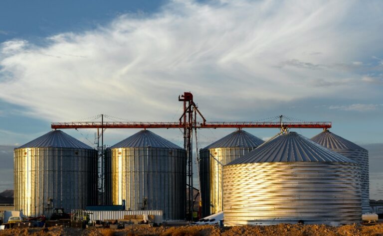
• Silo Discharger Valve: Controls the discharge of bulk material from silos efficiently and reliably.

• Double Gate Gravity Discharge Valve: Provides secure flow control with two gate mechanisms for bulk material discharge.

• Dosing Valve: Regulates the amount of bulk material discharged for accurate batching or mixing applications.

• Rod Gate Valve: Uses a rod-style gate to stop or allow bulk material flow with minimal leakage.

• Two-Way Converger Valve: Combines material streams from two inlets into a single outlet for process flexibility.

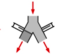
• Double Slide Gate Diverter Valve: Directs bulk material flow between different paths using sliding gate plates.

• Maintenance Gate Valve: Designed for easy access and servicing in bulk material handling systems.

• Shut Off Valve: Provides complete isolation of material flow in the closed position to ensure safe operation.

• Flow Controller: Adjusts the flow rate of bulk solids to maintain consistent process conditions.

• Double Dump Valve: Enables controlled dumping of bulk materials with two independent discharge gates.

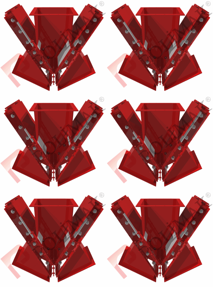
• 3-Way Diverter Valve: Directs bulk material to any of three discharge points, offering versatile flow diverting options.

• Aeration Rotary Throttle Valve: Combines aeration and flow control to manage challenging or sticky bulk materials.

Bulk Materials Handled by Custom Designed Valves

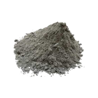
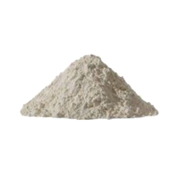
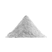
Cement
  
Starch
   
Minerals
  
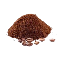
Coffee Powder
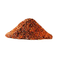
Spices
  
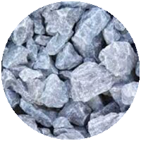
Limestone
  
Copper Oxide
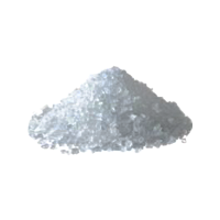
Salt
  
Sugar
  
Sand
  
Calcium Carbonate
Alumina
  

Image Gallery

Discover our amazing products today

Discover our amazing products today
Join our newsletter to stay up to date on features and releases.

By subscribing you agree to with our Privacy Policy and provide consent to receive updates from our company.

© 2024 Polimak. All rights reserved. Design & Development by brain.work
Contact Us
These valves are typically actuated by pneumatic actuators and are used to automatically open and close the product flow to discharge material to downstream equipment.
Installed below silos or hoppers, these valves are used for maintenance operations of equipment such as rotary valves, screw feeders, etc., that are positioned below the butterfly valve.
These valves are typically actuated by pneumatic actuators and are used to automatically open and close the product flow to discharge material to downstream equipment.
In this design, the butterfly valve is sandwiched between two flanges. Rubber sealing at both faces of the valve provides a tight seal between the flanges and the wafer butterfly valve.
One side of the valve has a bolted flange connection, while the other side features a built-in short pipe designed for fixing a flexible sleeve.
These valves have bolted flange connections on both sides, making them suitable for installation on silos, hoppers, screw feeders, and similar applications.
Bulk tanker trucks or open trucks can be filled with powdered materials delivered within FIBC bags. These systems generally consist of bulk bag discharging station, mechanical or pneumatic conveyor and loading bellow. Big bag discharge station transfers the bulk solid from big bag to conveying system. Conveying system transfers it to truck loading area. And loading bellow is used to fill tanker truck without any dust emission. Since truck loading operations are done within limited time, high capacity big bag discharge systems and bulk material conveying systems are used. For short distances, screw conveyors are preferred to transfer material from big bag discharge station to truck loading chute. For long conveying distances, pneumatic conveying systems provide better service. There may exist a storage hopper or silo above bulk truck loading bellow to compensate material flow between inlet and outlet. Bulk bag discharge and truck filling systems have automatic control system that monitors product level in truck and operates all equipment accordingly. Optional weighing system can be added to measure the amount of material that is filled to truck.
Big bag discharge systems can deliver dry bulk solids in powder and granular form to weighing and batching systems. The loading hopper of the weighing system should remain full during dosing and batching. Big bag discharge systems can monitor the product level in the loading hopper and maintain a constant level automatically. Depending on the dosing speed and conveying distance, mechanical conveying systems or pneumatic loading systems may be used. Dust collectors can be employed to prevent dust emissions during hopper loading, especially for materials with high dust content.
Dry bulk packaging systems are used to fill powdered or granular materials into bags, drums, jars, sacks, etc. Bulk materials delivered in big bags must be transferred to packaging machines without interruption. The loading hopper of the packaging system should remain full during the filling and packaging process. Big bag discharge systems can monitor the product level in the loading hopper and maintain a constant level automatically. Depending on the packaging speed, mechanical conveying systems or pneumatic loading systems can be selected. Dust collectors can be used to prevent dust emissions during hopper loading, especially for materials with high dust content.
Mixer automation systems are used to mix dry bulk solids according to specific recipes. Raw materials delivered in FIBC bags can be transferred to mixing units through a combination of conveying equipment and bulk bag discharge systems. Depending on the type of application, pneumatic conveying or mechanical feeding systems can be used to fill mixers. Big bag discharge stations can be manufactured with built-in dosing systems. The amount of raw material to be loaded into the mixer is automatically controlled with the help of a weighing and dosing system. Dust collectors can be used to prevent dust emissions during the mixer filling process.
Bulk material stored in big bags can be automatically filled into small bags. Big bag discharge systems come with optional built-in bag filling units. For low filling capacities, these units are installed below the big bag discharge hopper, providing a practical and cost-effective solution. Both big bag discharging and bag filling operations can be handled by a single, compact system. For higher bag filling needs, bag filling machines are installed near the bulk bag discharge stations. Pneumatic conveying systems or mechanical conveyors can be used to transfer bulk material from the FIBC bag discharge station to the bag or sack filling system.
Mechanical conveyors can be used for silo loading from big bag discharge stations. Screw feeders, bucket elevators, rotary valves, or chain conveyors are connected to big bag discharge stations to fill silos. The selection of conveying equipment directly depends on the conveying distance, height, transferred material, and capacity. Bucket elevators are preferred for high silos, while screw feeders are preferred for shorter silos and short distances. The big bag discharge system can be installed on top of the silo for faster filling. In this case, rotary valves or butterfly valves are better choices as they provide simple flow control. Dust collection systems may be required depending on the dust content of the bulk solid. During silo loading, air content in the silo escapes to the atmosphere and carries some dust along with it. Vacuum fans and jet filters in dust collectors prevent dust emissions into the environment. The collected dust is sent back to the silo, thus preventing product loss.
Pneumatic conveying systems installed after bulk bag discharge units transfer bulk material through conveying pipelines to fill silos. This configuration is useful in applications where high transfer rates and long conveying distances are needed. In production lines where raw materials are stored in warehouses far from storage silos, bulk bag discharge stations can be installed close to the warehouses, and pneumatic conveying systems are used to fill silos from long distances. This design reduces the need for forklifts and cranes for bulk material transfer on the production site and increases overall efficiency.

Pneumatic conveying systems used for silo loading utilize blower pumps or compressors. Motor power, pipeline diameter, and equipment selection depend on the type of bulk material, transfer distance, silo height, and transfer capacity. Level sensors, jet filters, and other equipment are installed on storage silos to ensure the proper operation of the silo filling system.
Pneumatic conveying systems installed after bag dump units transfer bulk material through pipelines to fill silos. This configuration is ideal for applications requiring high transfer rates and long conveying distances. In production lines where raw materials are stored in warehouses far from storage silos, bag dump stations can be installed close to warehouses, allowing pneumatic conveying systems to transport materials over long distances. This design reduces the excessive use of forklifts and cranes for bulk material transfer within the production site, improving overall efficiency.

Pneumatic transfer systems used for silo loading utilize blower pumps or compressors. Motor power, pipeline diameter, and equipment selection depend on factors such as the type of bulk material, transfer distance, silo height, and transfer capacity. Level sensors, jet filters, and other equipment are installed on storage silos to ensure the proper operation of the silo filling system.
Mechanical conveyors can be used for silo loading from bag dump stations. In this configuration, screw feeders, bucket elevators, rotary valves, or chain conveyors are connected to bag dump stations to fill silos. The selection of conveying equipment depends on factors such as conveying distance, height, material properties, and capacity. Bucket elevators are preferred for high silos, while screw feeders are ideal for shorter silos and short distances. Bag dump systems can be installed on top of the silo for faster filling. In such cases, rotary valves or butterfly valves are better choices as they provide simple flow control.

Dust collection systems may be required depending on the dust content of the bulk solid. During silo loading, air inside the silo escapes to the atmosphere, carrying dust particles with it. Dust collectors equipped with a vacuum fan and jet filter capture airborne dust. The collected dust is returned to the silo, preventing product loss and ensuring a cleaner environment.
The inlet skirt is an optional feature designed to extend the lifespan of the flexible connector sleeve. Its upper portion is attached to the outlet port of the upstream equipment and extends down into the bin activator’s inlet port. The primary function of the inlet skirt is to serve as a protective shield, safeguarding the flexible connector seal from wear and damage.
A vibratory motor is externally mounted to the bin activator. When powered, the motor generates vibrations that facilitate a steady flow of dry bulk materials within the system. Depending on the application requirements, one or two vibratory motors can be installed externally.
To accommodate a bin activator, the cone of a silo must be shorter than usual, resulting in a wider outlet. A flange supplied with the bin activator is separately welded to the silo’s outlet, slightly above the opening, at the production site. Once installed, the vibrating bin discharger is securely bolted to the flange, ensuring a stable and reliable connection.
Special spring suspension links and an engineered polymer seal work together to create a flexible connection between a vibrating bin discharger and the equipment positioned above it.

The proper design and installation of the polyurethane seal prevent it from slipping off and ensure a secure seal, eliminating the risk of dry bulk material leakage. Additionally, the seal offers high stress resistance and long-term durability, withstanding stresses caused by motor vibrations, pressure conditions, and other operational factors.

Externally installed spring suspensions provide full resilience to the vibrations of the cone head. They ensure that the generated vibrations affect only the cone itself rather than the upstream equipment structure.
An internally tapered, conical-shaped baffle plate is positioned at the center of the bin activator’s diameter. The baffle is rigidly attached to the equipment body using structural steel components. It facilitates bulk material flow from upstream equipment by directly inducing vibrations into the material.

A secondary deflector plate reduces the weight of the bulk material in the lower portion of the bin activator by acting as a wedge beneath the material, directing it around the areas adjacent to the cone’s surface.

Polimak baffle plates are available in various configurations, including convex and cone plates, and in different angles (15°, 30°, 45°, or even 60°) depending on the flow characteristics of the handled bulk material and the specific application requirements.